Thursday, December 12, 2013
Finally, a Maze! That Tilts!
Saturday, November 23, 2013
Week of Nov 18
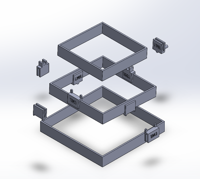
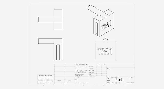
This week the assembly of the final project was completed in solidworks, following the finalization of our design. The parts are ready for printing, we are just meeting once more to confirm there is nothing else we need to add and to confirm that the total volume of the parts, with support structures, are under the four cubic inch limit. We are still rounding up the last of the extraneous materials for the project.
Tuesday, November 19, 2013
Week of Nov. 11th Progress Summary
This week we meet to finalize our concept and make sure all members were in agreement over our goals. We drew up an initial sketch of the physical mechanism and finished writing the code that will control the mechanism from three separate Arduino boards. We discussed what needed to be done for the following week, and allocated further software development to Maulik Patel, the modeling in Solidworks to Justin Wood, and gathering of materials and blog maintenance to Damien Laird.
Fundamental Mechanism
The fundamental mechanism of the tilting maze is two frames, each rotated by a servo motor on perpendicular sides. This allows the users to tilt the maze in two directions. The above sketch illustrates this concept. The frame and table itself will likely be made laser cut acrylic or cardboard, while the stand will be 3d printed.
Subscribe to:
Comments (Atom)


